- As shown in the image below, remove the screws marked with the red circles.
 Tool: 3 mm hex key
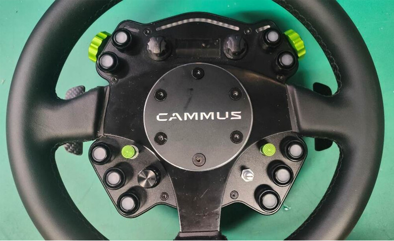
- After removing the screws in the previous step, lift off the steering wheel. Then remove the six screws indicated by the arrows in the image below.
Tool: 2 mm hex key
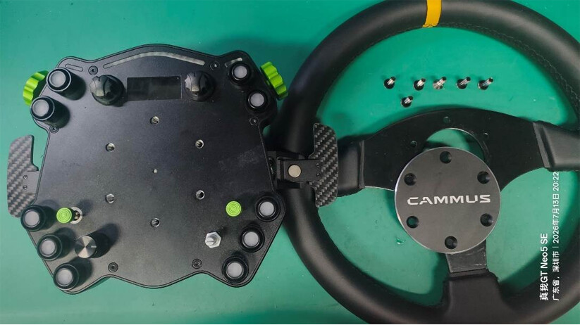
- Once all the screws from the previous step have been removed, gently hold the raised buttons or rotary knobs and carefully lift the front cover slightly.
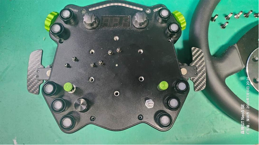
- After lifting the cover, you will see the wiring harnesses on both sides at the rear of the cover, as shown below. Carefully pull the harnesses outward to disconnect them.
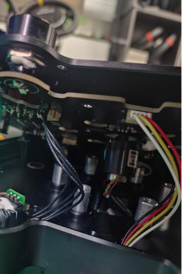
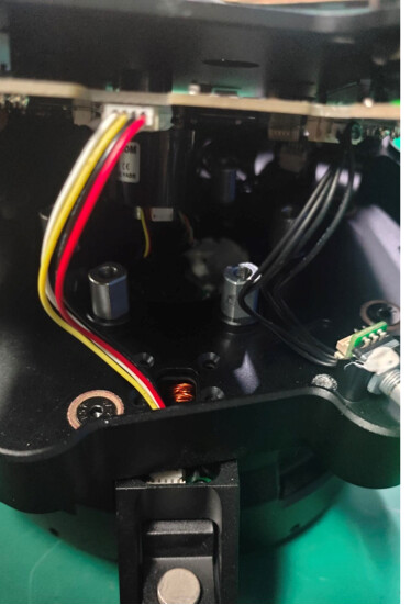
- After disconnecting the wiring harnesses, set the front panel aside. Then remove the screw indicated by the arrow in the image below (the left and right sides are identical—removing either side is sufficient).
Tool: 2 mm hex key
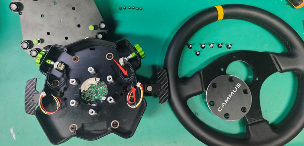
- Remove the screws of the same type indicated by the arrows in the image below.
Tool: 3 mm hex key
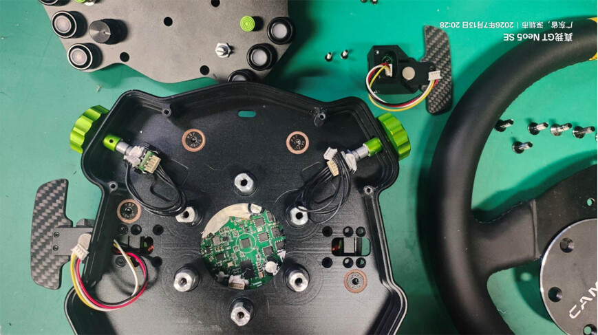
- After removing the screws from the previous step, lift out the HUB base and place it aside.
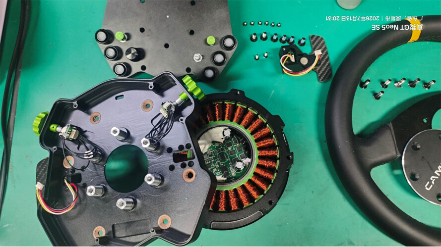
- As shown below, use a utility knife to carefully cut and remove the heat-shrink tubing at the location indicated by the arrow.
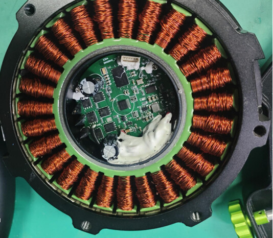
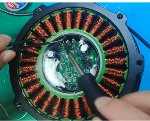
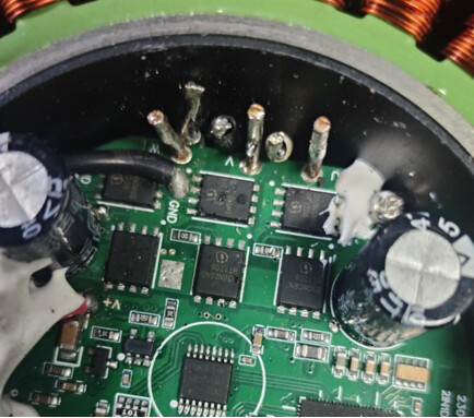
- Using a soldering iron, desolder and disconnect the wires at the location indicated by the arrow.
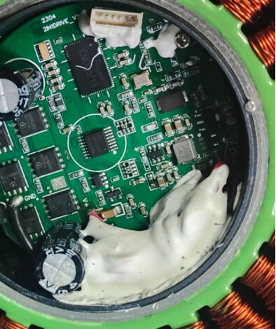
- As shown in the lower-left image, use tweezers or a similar tool to carefully remove the white adhesive indicated by the arrow until it is fully separated, as shown in the lower-right image.
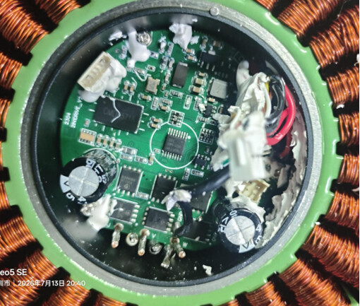
- As shown in the lower-left image, remove the screw indicated by the arrow.
Tool: PH1 Phillips screwdriver
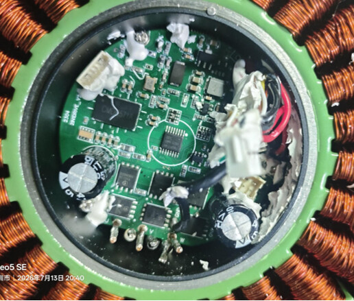
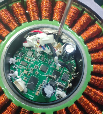
- After removing the screw, hold the black wire and slowly lift the PCBA upward.
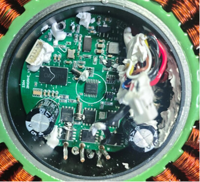
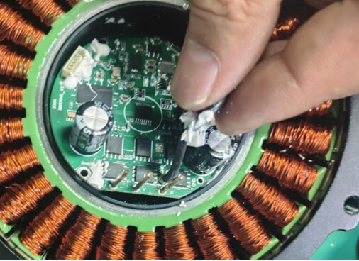
- After lifting out the PCBA as described in the previous step, place it aside. Then remove the screw indicated by the arrow in the lower-right image.
Tool: PH1 Phillips screwdriver
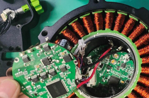
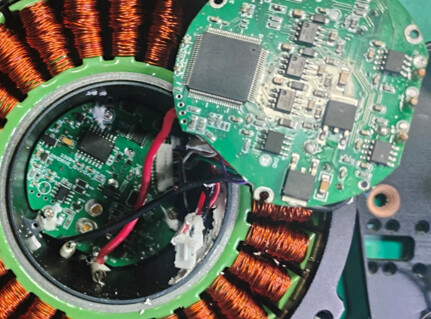
- After removing the screw, turn the device over as shown in the lower-center image. Press the connector until it loosens and slides backward. Then turn the device back over and gently pull the red and black wires, as shown in the lower-right image, to remove the PCBA.
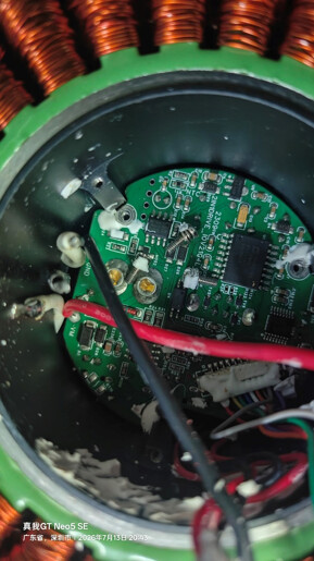
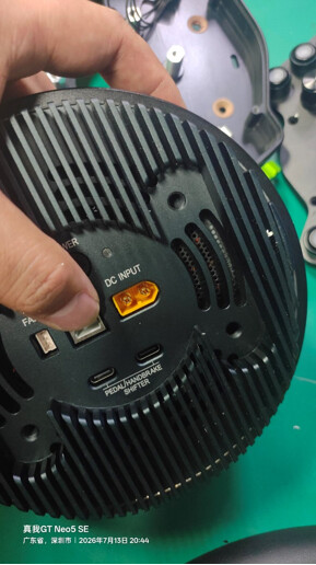
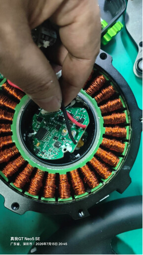
- After completely removing the PCBA, measure the resistance of the resistor shown in the image. The normal resistance should be 25 Ω. If the measured value is abnormal, please contact CAMMUS for assistance.
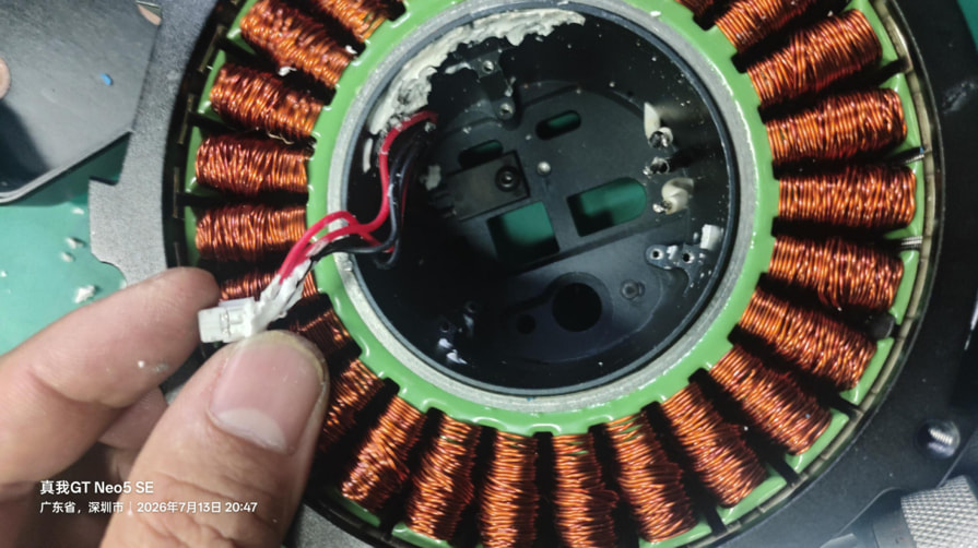
- Finally, install the new PCBA by following the above steps in reverse order.
 You can also download the PDF version of this replacement tutorial for offline reference:
CAMMUS-C12-PCBA-Replacement-Tutorial.pdf
 If you encounter any issues during the replacement process, please contact our support team by submitting a ticket through our Support Portal: